|
Cl
REMOVAL
FROM CAR
Acces
to the gearbox for checking and topping-up oil level is from beneath the
car. Removal of the front tunnel by withdrawing side screws can aid
servicing and inspection. For repair or overhaul of the gearbox,
however, it is necessary to remove it from the car, and this is
accomplished as follows.
-
Drain
gearbox of oil, preferably when hot, by removal of drain
plug. Take out the side (level and filling) plug to aid flow.
-
Remove
tunnel front and rear covers, from inside the car by withdrawing
the fillet "Phillips" screws and lift clear.
-
Disconnect
gearbox from bell housing, after chocking-up rear of engine
to support weight.
-
Free
Propeller Shaft rear end by removing the four bolts from the rear
universal joint. This permits the propeller shaft to be lifted
at the rear and withdrawn rearwards.
-
Remove
Transverse Mounting Bolt from the bush mounting beneath the
end of the rear cover.
-
Disconnect
Speedometer Cable by unscrewing the knurled barrel at the right
hand side of the box rearcover.
-
Lift
Gearbox Upwards and Rearwards, clearing rear mounting with minimum
of lift to avoid undue strain on the engine water hoses, choke and
control cables, linkages etc. and when free from the bell housing,
allow rear of engine to settle gently on to support chocks. The
gearbox should then be free to lift on to bench. The use of
suitable wooden cradles will assist all work on the bench.
|
|
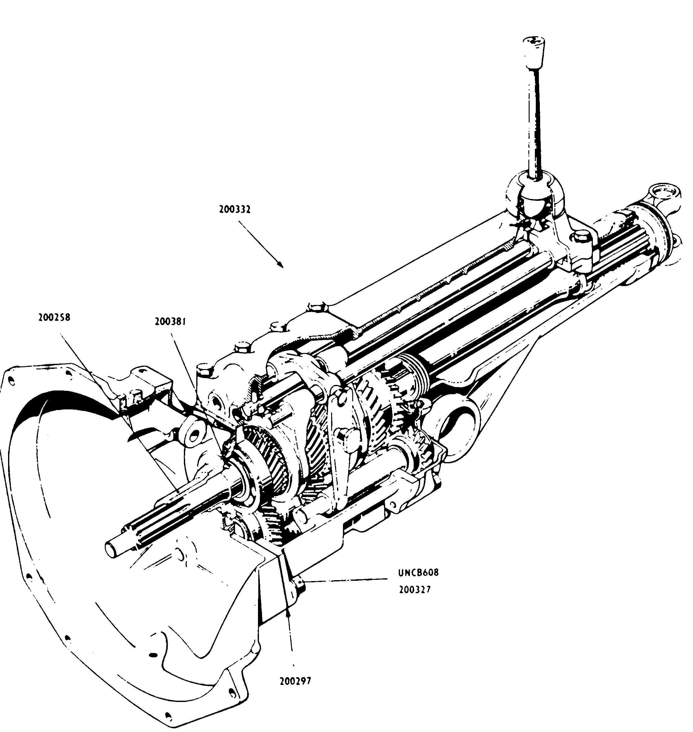
C2
DISMANTLING
THE GEARBOX
-
Remove Top Cover
Unscrew the nine bolts securing the top cover and lift clear
complete with gear lever, taking care not to damage the cork seal.
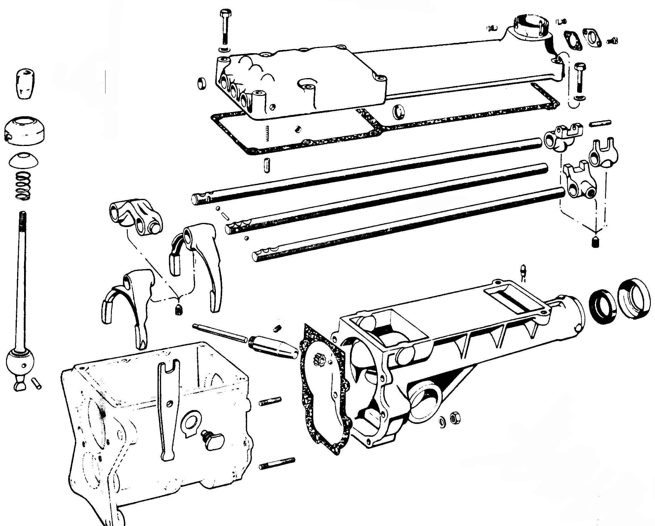
To Dismantle Top Cover
-
The gear lever is removed by depressing
the base cap, and an anti-clockwise turn will free its bayonet
retention.
-
The three shift rails are freed by the
removal of their retaining grub screws.
-
All shifting and selector fork castings
are secured to the shift rails by grub screws wich are unscrewed
to dismantle.
-
Remove Gear Cover
Remove the six retaining nuts and draw clear of the fixing studs
in the rear of the gearbox housing. Remove the sealing gasket
intact.
To Dismantle Rear cover
-
The rear cap is withdrawn to remove the
dus proof radial seal ring.
-
An internal white-metal bush supports the
driven end of the propeller shaft and this is renewed by shrinking
in a replacement. It is not normally removed.
-
Remove Reverse Lever, reverse Gear and
shaft
Free lock washer, and remove the bolt with two flats located on
the side of the gear case. The reverse gear and shaft should
then lift out.
To Dismantle Geverse Gear
Remove, in this order, the spring clip, thrust washer, needle
bearing and the 17 toothed sliding gear with end thrust washer.
-
Remove Primary Shaft
See that a flat on N)1 synchro gear lies parallel to the top of
the case, to ensure clearance of the laygear.
Use a thin, flat brass drift applied to bear on the primary shaft
flange to drive the complete assembly forwards. Care should be
taken to avoid jarring the needle bearing or this may fall out of the
gear housing.
To dismantle Primary Shaft
Remove spring retaining clip, shim and split washer to free the
ball bearing. The gear and shaft are integral, with the gear end
face bored to house the needle bearing.
-
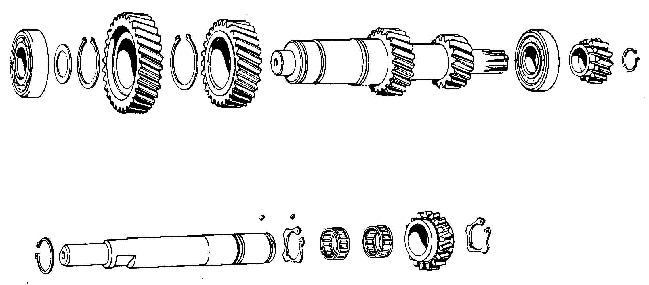
Remove Reverse Gear from Mainshaft
This is the cluster projecting to the rear of
the gearbox housing, formerly within the gear cover.
Remove the spring clip from immediately behind
the helical speedometer driving gear.
The speedometer gear, collar, reverse gear, shim-housing and bearing
retainer with shims will all come off rearwards over the tail of the
shaft.
Fig C.3
-
Remove Mainshaft and Rear Bearing
Expand and free the large rear bearing
retaining clip from its seat in the periphery of the bearing agains
the rear face of the gearbox housing.
To extract the rear bearing, which is a press-fit in the gear case
housing, it is essential tu use the special bearing extractor (see fig
C4)
Before removing the bearing, first remover the 12 toothed reverse gear
from the rear end of the layshaft, where it projects through the rear
of the gear case (below and to the right of the mainshaft), by removal
of the retaining clip.
This is necessary to make room for the head of the bearing extractor
tool, which is then engaged in the peripheral bearing groove from
which the retaining clip has just been removed.
The two valves of the extractor tool are then locked to the bearing by
means of the outer sleeve, which holds them together.
The threaded screw at the other end of the tool is brought to bear on
the end of the shaft, and progressive tightening by the hand-toggle
will cause the bearing to be drawn rearwards, and freed.
If difficulty is experienced in engaging the tool head in the bearing,
it may be necessary to use a soft drift to tap the shaft rearwards
from its other end, to shift the bearing and its groove out until the
tool can engage.
The mainshaft, complete with main cluster, will now lift from the box
by careful manoeuvring, and the tail of the mainshaft, drawn forwards
and upwards will follow.
To Dismantle Mainshaft
-
The front cluster is removed in the
following sequence; first speed thrust-washer and first speed
gear, needle race from within the first gear, thrust washer, first
and second speed synchro mechanism.
Lift the flat locking key from its keyway, remove the thrust
washer and the second speed gear with its split needle race.
This completes dismantling as far as the shaft flange.
-
The rear bearing having been removed
(6-above) there remain only the third and fourth speed synchro
mechanisme, the third gear thrust washer and locking key.
This completes dismantling of the rear cluster.
To dismantle Synchro Bodies
The parts separate easily. Take care not
to lose the spring-loaded balls from within the assemblies.
Fig C.4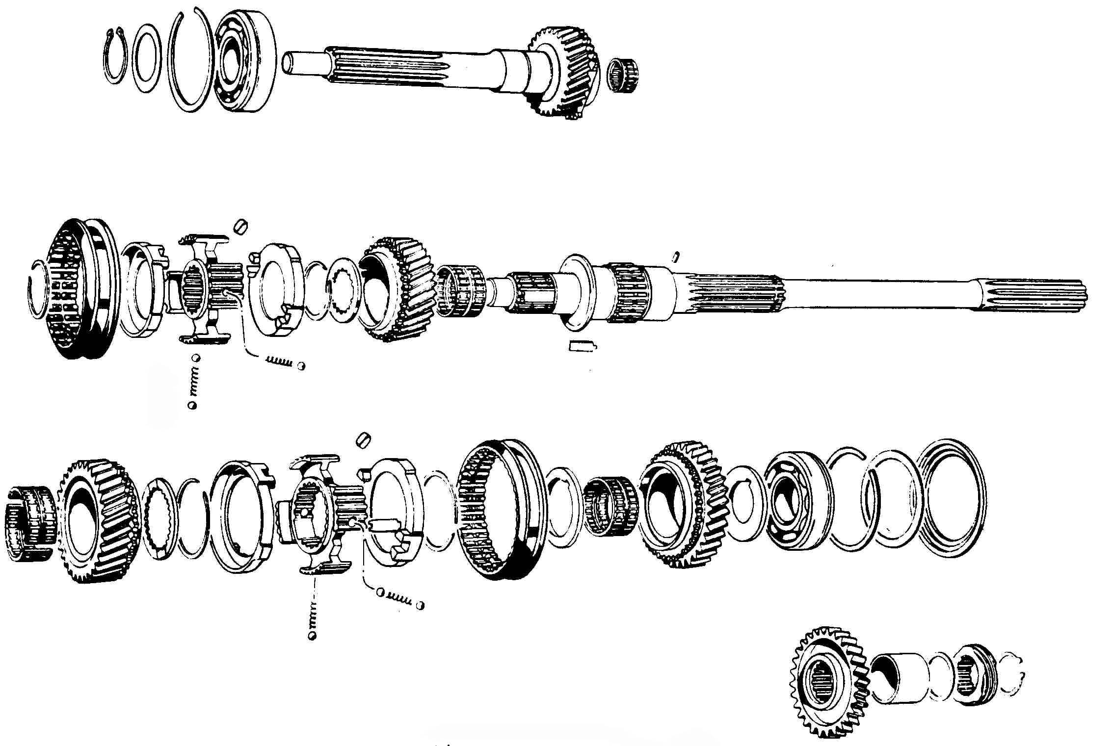
-
Remove Layshaft
The external spring clip and reverse gear have already been
removed (6-above). Now push the layshaft to the rear and remove
the roller bearing from outside the gear case.
The shaft should then move forward and upward to lift clear of the
box, complete with gears and front bearing.
To Dismantle Layshaft
-
Remove the inner half of the rear thrust
bearing
-
Remove the front bearing
-
Remove, in sequence, the spring clip,
fourth gear, second spring clip, third gear. The first and
second gears are integral with the shaft. (Note that fourth and
third gears are a shrunken fit and should be heated to not more
than 158°F (70°C) to facilitate removal.
C3
REASSEMBLY
OF THE GEARBOX
The
sequence given should be followed inGearbox conjunction with the
check-points, gauge tensions and tolerances quoted.
-
Refit
the Layshaft - reverse order to the dismantling procedures
-
Refit
the Mainshaft - Similarly
-
Refit
the Primary Shaft - Similarly
-
Refit
the Reverse Lever
See that the radius on the top half of the lever is towards
the lever securing bolt, and refit with the lock washer.
(The lower adjusting screw, which sould have remained correctly set,
must bear on the lever when this is pushed against the reverse shaft).
-
Refit
the Gearbox to the car - Reverse to the removal instructions
Reassembly
Check Points
-
See
that the rounded nose of each gear is facint in the direction of
the mesh.
-
Check
shaft end-float and other tolerances given below.
-
Heat
leyshaft gear on hotplate within limits stated.
-
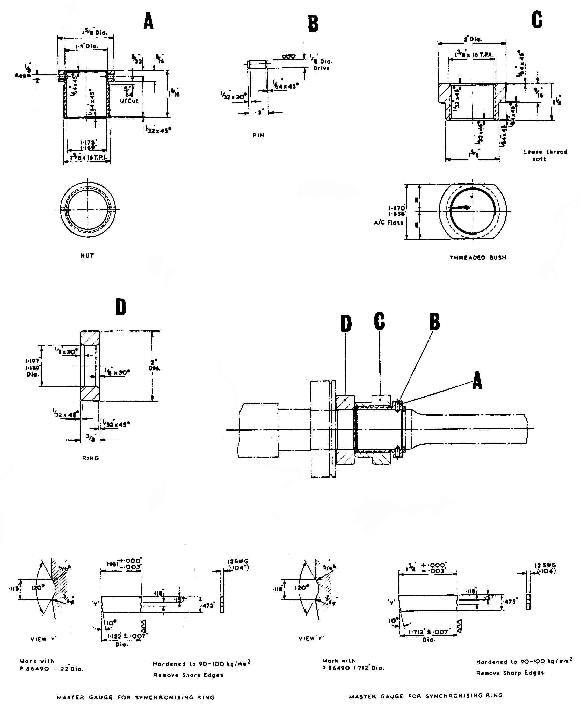
Check
synchro body tensions carefully with the gauge made to Dwg. P86490
(See fig C5)
-
It
is important, when fitting the first and second synchro body to
see that the locking device is on the second gear and NOT in the
first gear. The function of the ZF-Synchro-lock is based on
the principle that the parts to be coupled must have obtained
equal rotational speed before they can be smoothly engaged.
During the procedure of gear changing the axial sliding of the
sliding sleeve on the synchronizing body must therefore be held
back by the locking device until the parts to be engaged have
obtained aqual rotational speed. Not until the contact
surfaces, which are pressed together at the instant of changing
gear, have caused the parts on the engien side to turn at the same
speed as the parts on the vehicle side, can the locking device be
pressed back by the persistetn pressure from the sloping inner
theeth of the sliding sleeve to their original position.
Wit the lock released the sliding sleeve can move in the direction
of the gear. Direct connection between driving shaft and
main shaft is only effected in fourth gear. (It should be
understood that when the synchro body comes into contact sith the
gear it rotates the synchro mechanism, and only when the speeds
are dynchronized is ite possible to change gear). Not that
there is synchro locking on second, third and fourth gear, NOT on
first gear.
Fitting
Tolerances
The
following figures should be used for checking gear assemblies.
First and second speed synchro mechanism tension should be checked with
gauge P 86490 at 14-15 kg (31-33lb)
Third and fourth
speed synchro mechanism tension should be checked with gauge P 86490 at
13-14 kg (29-31lb)
Clearance between synchro bodies and gears 7-9 mm (0,273-0,351 in).
Clearance on all gears (end float) 0-2 mm (0,000-0,078 in)
Clearance between synchro ring and selector forks 1-3 mm (0,039-0,117 in)
Clearance between race an gears 0,01-0,012 mm (0,004-0,005 in).
Clearance between speedometer drive and bush 2 mm (0,078 in).
Clearance between gear lever and selector fork 2-3 mm (0,078-0,117 in).
Clearance between rear bush and propeller shaft 1 mm (0,039 in).
Clearance between gears (back lash) 0,002-0,003 mm (0,001-0,0015 in).
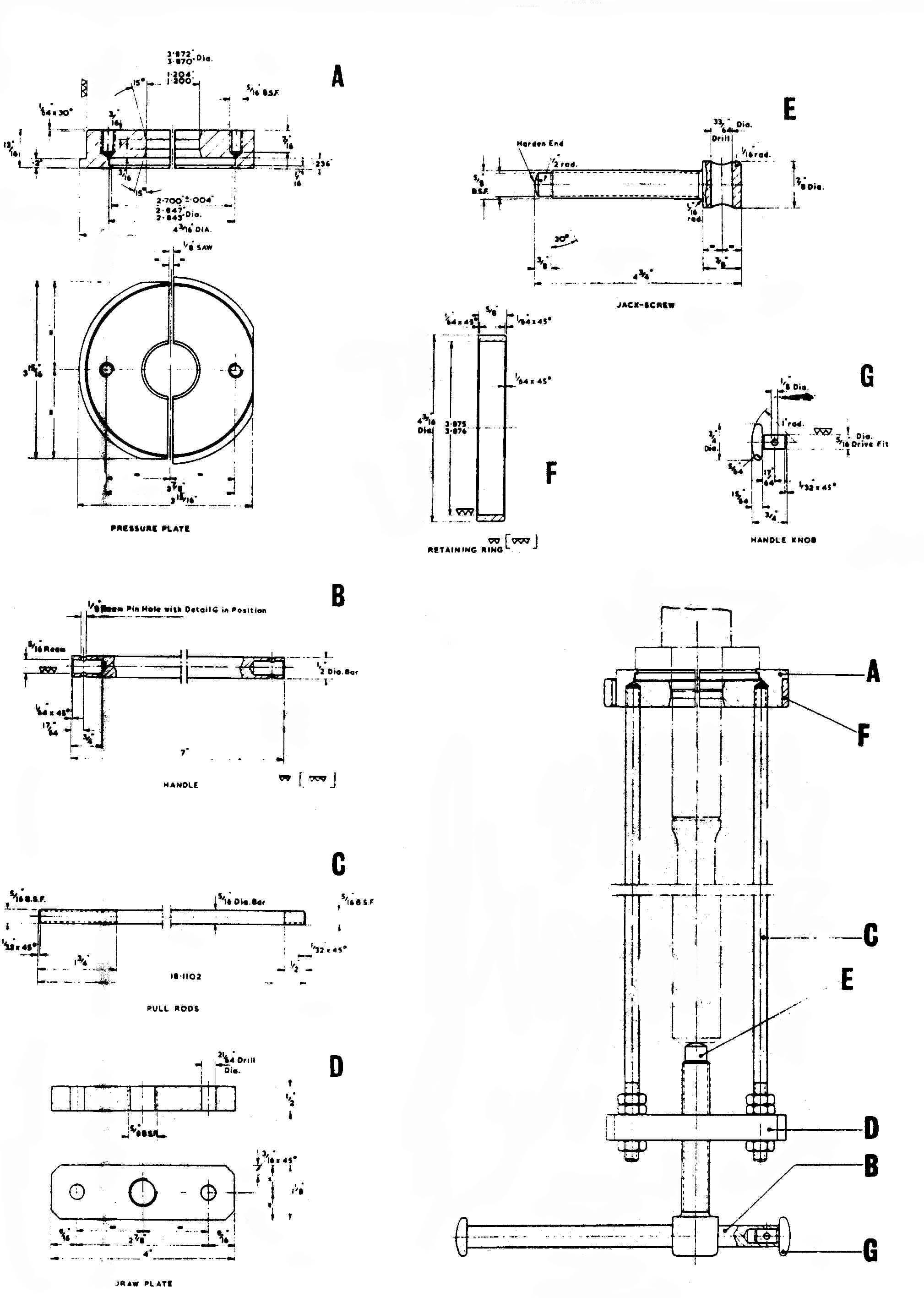
Fitting
Tools
The
three special tools are as follows:
Extractor
Fig C5, used to remove rear mainshaft bearing.
Tool Fig C.6 used to replace rear mainshaft bearing.
Gauge Fig C. used to check and set synchro pressures.
|